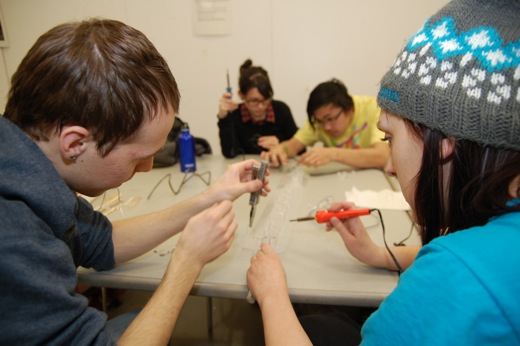
We’re in week 3 of this LED sign project, and we now know how to finish it up. We had previously soldered all the anodes on the LEDs, but we were a bit confused about the connections of the cathodes and resistors. As we had been working off of a MAKE video, which breezed over the connections, we realized we really weren’t entirely sure of how to make those final connections.
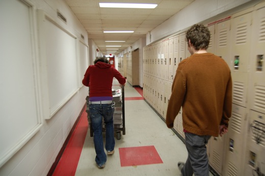
Before the soldering began though, we had to move the huge pile of bundled newspapers we got, courtesy of Mike. Last week, he had suggested that we could get some extra papers to do some as-of-yet undefined future project, but we hadn’t realized how many we would receive.
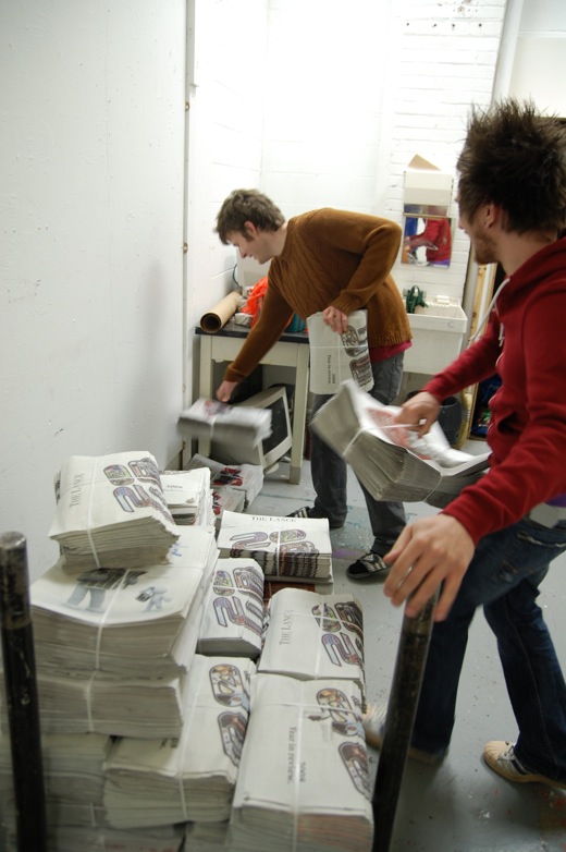
Steven and I got a cart from the sculpture room to begin moving.
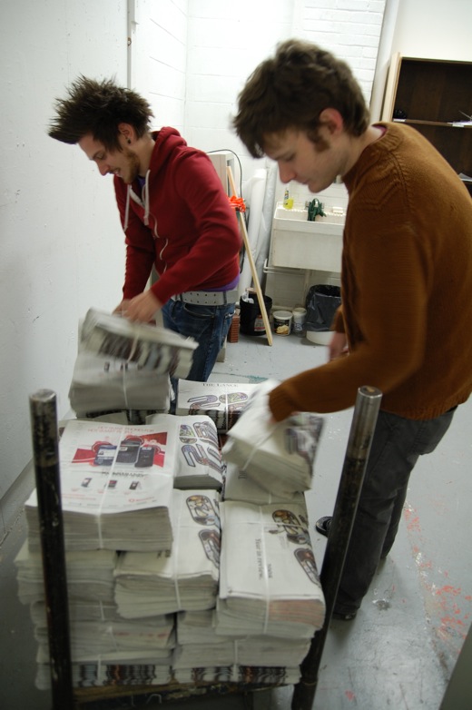
We piled the papers against the wall in my studio.
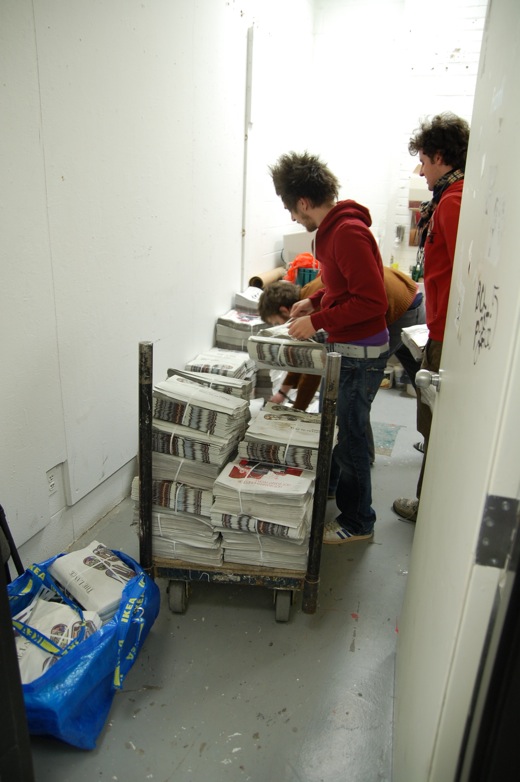
Mike lent a hand on round two. The papers had been piled outside on a bench, which made the amount of papers we had seem insanely huge. We were laughing at how ridiculous it might be to find a use for all of these in the next few months.
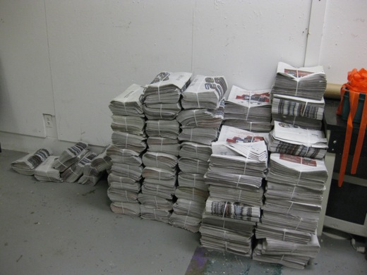
The final stack in my studio isn’t so bad.
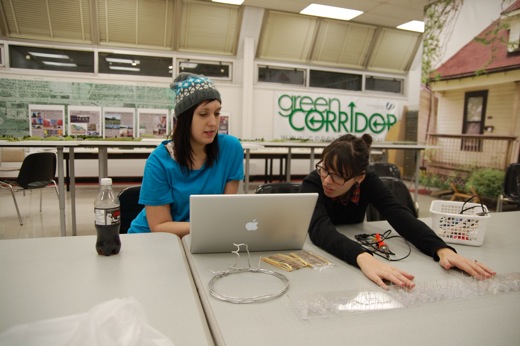
Meanwhile, Michelle and Danielle watch the video from MAKE, trying to figure out where the resistors go and how many there needs to be.
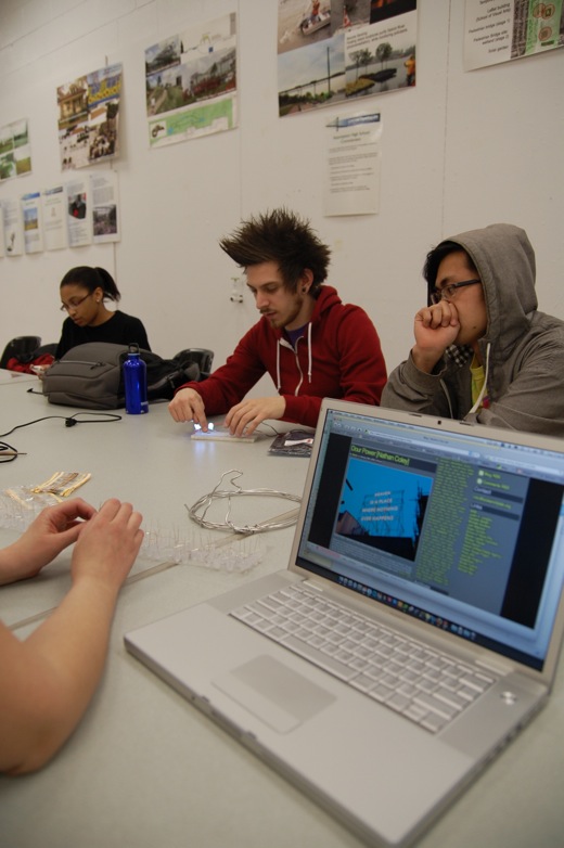
I took out my breadboard and revisited the original mock-up Michelle and I had done for the circuit, though somehow, we ended up confusing ourselves into changing up the wiring.

We were trying to determine how to make what was happening on the breadboard happen on the back of the plexiglass sign.

Immony doublechecked some wiring specifics.
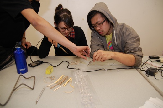
Celia, Danielle, and Immony prepared to begin soldering.
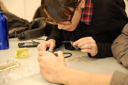
Danielle took on soldering, while Immony held the resistors in place.
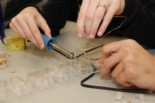
We had talked ourselves into thinking the LEDs only needed a resistor between them, rather than one for each cathode. As the anodes were already all soldered, it just left this path of cathodes to connect with resistors, or so we thought.
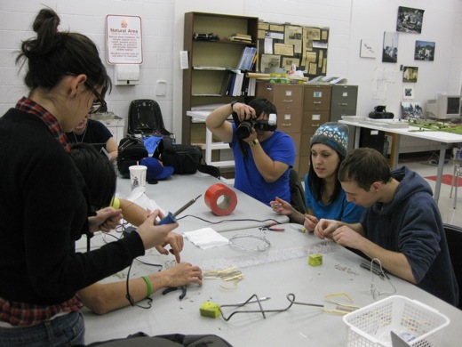
Racing to finish the soldering. At this point, we decided to stop and test the progress.
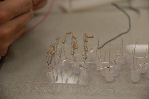
Unforunately, things were really wrong, so we blew a few LEDs.
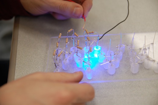
We couldn’t understand what went wrong, but we also could really explain why we thought the wiring we had done would work either, so we knew we had to rethink things.
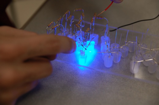
We tested both sides of the sign, but the results were the same, the resistors weren’t resisting properly, and the circuit wasn’t make any sense, or lighting all the LEDs.
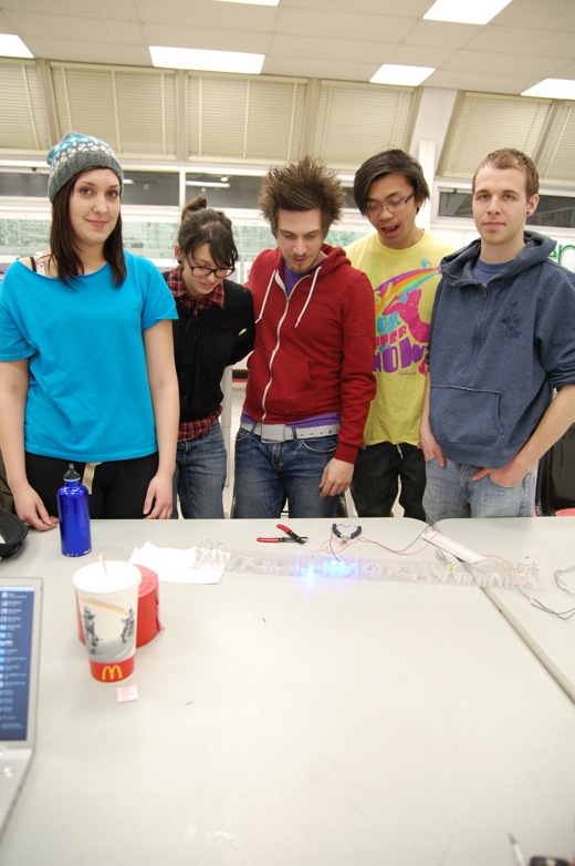
After some more testing and reviewing why the wiring on the breadboard worked, we realized that each LED did need its own resistor and the power for each LED would have to come off of one main positive lead. Each LED would then be fed off of that main positive lead, which we could run on the top and bottom of the sign’s plexiglass, making the wiring neater as well. Above, you see our victorious 3-LED test wiring in the middle of the sign!!! We’ll go back and fix the resistors, test to see which LEDs are burnt out and then finish it up (hopefully soon)!

i hope you were able to sort it out and that the LED’s were soldered ok on the plexi. i missed being there though but had a good time at phog for the tech night.
I’m glad we finally figured out how to do this. Now it’s only a matter of time before our sign is fully functioning!
Yes!!! Ready for another Monday morning soldering party?
count me in!