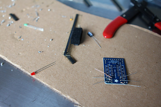
Although it’s been a while since I last worked on this project, things are continuing to move along. I finally assembled the Ladyada XBee adapters and successfully passed a message between the two XBees.
So, I’m not the best solderer and the first adapter I worked on suffered from an overusing tip on my soldering iron, which made heating up the solder with the tip of the iron next to impossible. There were also some issues (that remain unresolved) in terms of configuring the XBees, but thankfully that step seems to be unnecessary (at this point anyways).
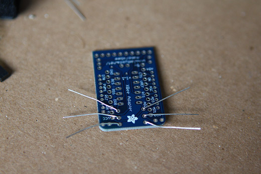
The XBee adapter with the 3 necessary resistors waiting to be soldered. I had ordered the adapters and XBees a while back, and had been reading up on them, but I’m increasingly finding that I’m at the point with this project where reading without doing isn’t that helpful.
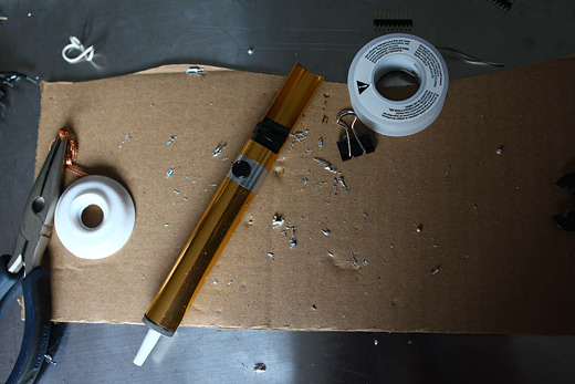
It took much, much longer than it should have to solder the two adapters, and I used the desoldering tool a lot more than I should have needed to, but it all worked out. Above, the results from those two efforts of soldering.
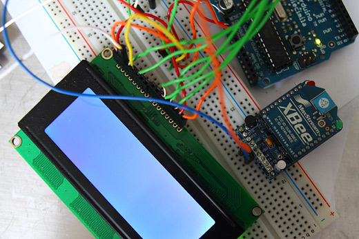
In the process of my adventures in soldering, I think I fried the green LED slightly, as it was difficult to see when it was flashing at first (it will flash to indicate it has power and is working).
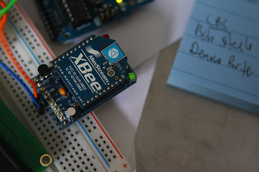
You can see here just how little the LED actually lights up, but it’s enough to confirm that it is indeed working.
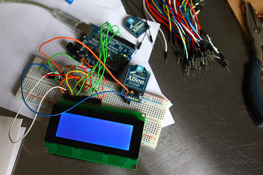
So, at this point, I was just powering up the XBee, while maintaining the same wiring for the LCD. I figured that it would be kind of pointless to remove the LCD as eventually they’d need to be connected to the same Arduino / breadboard anyways.
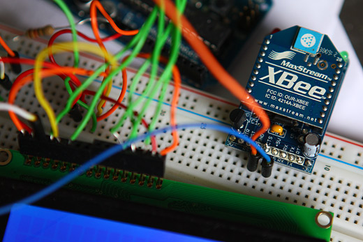
A close up of the XBee adapter simply connected to the +5v and ground.
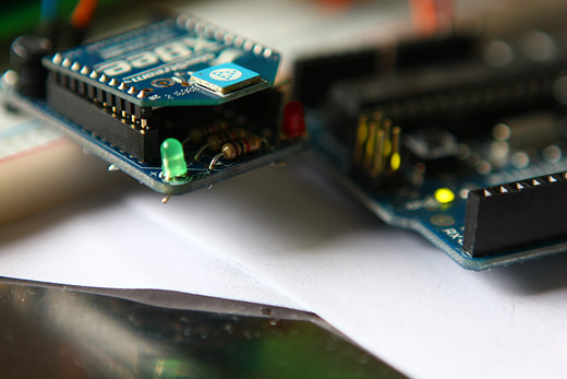
I also messed up on some part of the adapter, in terms of the connectivity to the XBee itself — it may be that because I broke off one of the pins on the pin-rows while assembling the adapter that it’s now fussy, making it necessary to position the XBee just right to get it working. Thankfully, the other adapter is totally fine.
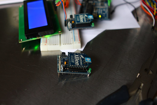
The second XBee adapter assembled.
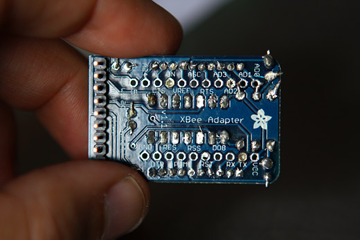
My fairly shoddy soldering job up close.
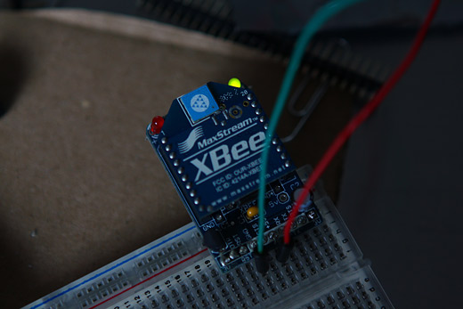
I hooked up the second adapter to the second Arduino (Duemilanove) and a breadboard to test — success!
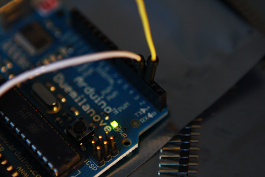
The second Arduino setup to use the software serial library, with the TX and RX on pin 2 and 3.
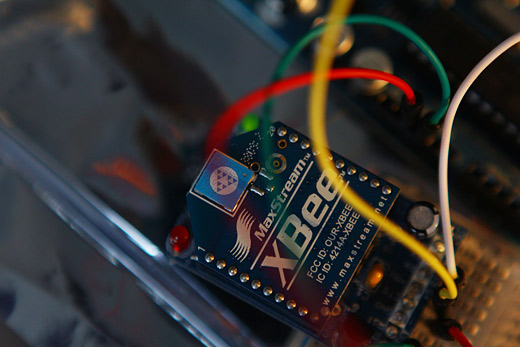
The XBee connected to ground, +5V, RX and TX. I had some significant difficulties in trying to configure the XBee via terminal in OS X. It wouldn’t seem to connect using screen, which was recommended here; instead, it would just hang. Still haven’t figured out why, but eventually I realized that, stupidly enough, I had the RX and TX mixed up on the sending XBee, possibly occurring when I switched over to using the Soft Serial to communicate. I think that I’ve since confirmed that this wasn’t the reason screen wasn’t working, but it’s still a mystery to me.
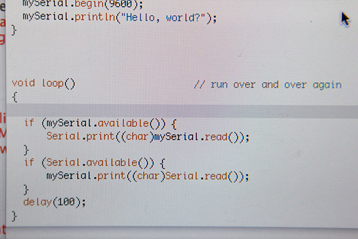
The software serial library Arduino script to do a simple test. Typing into the serial monitor in the Arduino IDE would pass along the message to the second XBee.
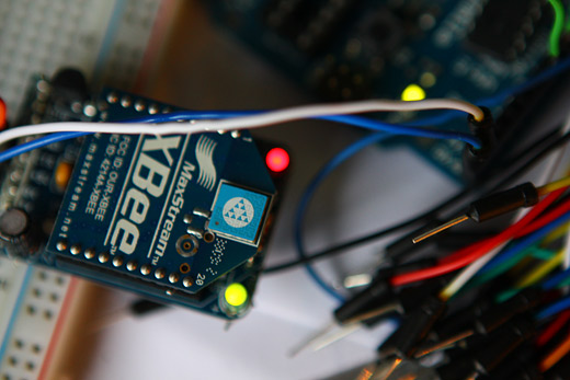
So, even though I had some fairly major stupid mistakes (wires mixed up) at first, once corrected, the red light on the second XBee turned turned on, which means successful transmission!!!
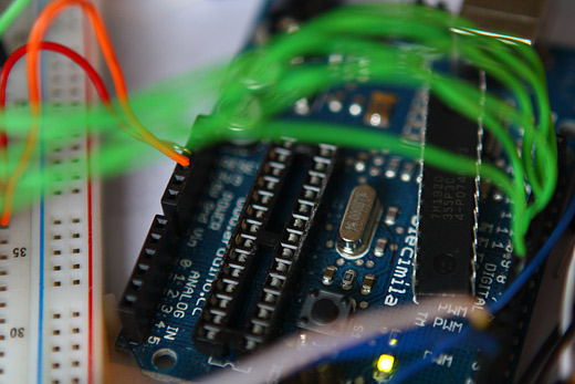
I de-chipped the Arduino on the receiving end to essentially turn it into a FTDI converter. Technically, right now, I think I have these on the wrong ends — that is, I would need the de-chipped Arduino or the FTDI converter cable on the sending end, to allow the receiving end to have the Arduino with the code to process the sent text and then display on the LCD.
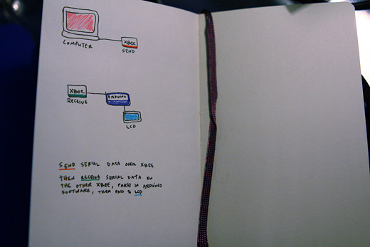
And finally, the diagram of where I’m hoping to move the project — obviously it’s fairly basic, but right now, I’m missing the connection to the LCD in terms of where the project is actually at. I need to think this through and look at the many examples online to figure out how the LCD receives the serial data. Is it the case that the XBee can just forward serial data to the Arduino?
More soon, I just need a few hours of time in a nice block, and I should be able to start sending messages wirelessly to the LCD!
—
Annotated Bibliography
http://hyperradiant.net/blog/2009/02/sending-serial-commands-to-xbe.html (set up XBee in terminal, OS X)
http://www.digi.com/support/productdetl.jsp?pid=3434&osvid=0&s=367&tp=3 (XBee read-me)
http://antipastohw.blogspot.com/2009/01/xbee-shield-to-xbee-shield.html (setting up two Xbees)
http://www.youtube.com/watch?v=-U8fxOf8JA8 (wireless LCD, sends via an XBee to an XBee connected to Arduino / LCD)
http://www.ladyada.net/make/xbee/wiring.html (instructions that explain the XBee shield)
http://www.ladyada.net/make/xbee/point2point.html (basic point-to-point networking, sending messages using softserial)
http://www.arduino.cc/cgi-bin/yabb2/YaBB.pl?num=1229180251/10 (tool for configuring XBees)
http://teenybreeny.wordpress.com/2009/04/12/xbee-going-wireless/ (more XBee configuration)
I would like to thank the Canada Council for the Arts for their generous support.


I think I have found out why the terminal hangs when configuring via screen. I was following the recommended datarate of 9600, but when I tried 57600 it would allow me to enter command mode.
Are you familiar with the Vex robotics platform?
I am working on and help with connecting a Xbee node to the Vex Cortex so I can achieve multi-robot communication.
Do you think you can help?
Great post. Don’t you love it when you get the wires mixed up and you have no idea why there is no transmission?! Are there other places you recommend to find the Xbee adapters online? Looking forward to future posts.